The ongoing tariff situation has directly impacted our supply chain and manufacturing for the Wingnut Tech LED Controller. We have looked around extensively for alternatives, but there are currently no options that would allow us to continue offering our products at the quality and value we require.
In the end, we have made the difficult descision to discontinue manufacturing and selling the Wingnut Tech LED Controller for the forseeable future.
We will continue to offer support for our past customers to the best of our abilities, and we've archived our FAQs and other info on this site for reference.
Thank you all for sticking with us throughout the years.
FAQ
Does the Night Radian LED Controller work with both the BNF and PNP versions of the plane?
The PNP (plug and play) version of the FT Night Radian does not come with a receiver, you have to supply your own. Because of that, this module is completely compatible, as long as the receiver you install has a spare channel that it can plug into.
The most recent version of the BNF (bind and fly) EFlite Night Radian comes with the newer Spektrum AR631 receiver, which is completely unlocked, and only needs a channel assignment on the transmitter.
The original FliteTest BNF (bind and fly) version of the Night Radian came with a Spektrum AS3X 6 channel receiver (AR636), but channels 4 and 6 are not assigned to any channel in the receiver. Channel 5 is used for SAFE and AS3X functions. Channels 4 and/or 6 can be assigned, but that requires a USB cable and the Spektrum app in order to do so. This is not a limitation of my LED controller, this is a limitation of the receiver that was installed in the plane by the factory. If you google "as3x programming cable" you will find links to buy the cable, as well as articles and blogs from people who have done it.
Here are some helpful links:
Here’s the programming cable you need to unlock the Spektrum receiver:
https://www.spektrumrc.com/Products/Default.aspx?ProdID=SPMA3065
Once you have the cable, the software can be found here:
http://spektrumrc.cachefly.net/apps/spektrum_programmer.html
And yes, there are a number of posts from others that have done this. Here is a link to one:
https://www.rcgroups.com/forums/showpost.php?p=44635411&postcount=29
And an entire series of videos from Spektrum that show in depth how to program their receivers. Video 4 in this series is probably where you want to start.
https://www.youtube.com/watch?v=LnYiKgrL_bU
The Night Radian LED module is powered through the receiver, and it powers all the LEDs from that too. Won’t that draw too much current and cause a brownout in my radio gear?
When designing the Night Radian LED Controller, we wanted to eliminate the need for drawing power from the balance plug of the battery. Because of this, we were very careful along the way, and constantly measured current draw of the system. With a stock Night Radian setup, I could turn on all LEDs to their brightest white setting, stall both servos, and command full deflection of elevator and rudder, and I was consistently only drawing 2.1 to 2.2 amps from the battery to power everything. The airplane comes with a 3 amp BEC, so there was more than enough margin available for all the electronics to be powered through the plane’s onboard BEC.
That being said, if you have modified the radio gear or replaced the servos, I strongly recommend you check your current draw with a watt meter, LEDs on full bright white, stalling both servos commanding full deflection, to make sure you are still under the 3 amp limit of the BEC. If you have replaced the stock ESC, and it has a lower BEC rating, then you will need to power the LED Controller from a separate BEC.
How do I use the altitude and variometer function on this controller? Do I need a radio system that has telemetry?
This LED controller does not interface with any telemetry systems for sending data back to your transmitter. It simply changes the LEDs to indicate your relative altitude and rate of ascent/descent.
There are a number of “shows” on this controller, and they are selected by turning the rotary knob on your transmitter slowly from low to high. The first show, at the knobs lowest setting, is simply all LEDs off, only NAV lights on, if they are enabled. As you rotate the knob, there are several solid color shows, flashing and/or strobe shows, chase shows, and finally, at the knob's highest setting, you have the altitude show. The altitude show will read the altitude when the unit is first powered up, then, as the altitude increases, it will start lighting up more LEDs on the wings, up to 400 feet AGL, where all the wing LEDs will be lit up.
If half the wing is lit up, you are at about 200 feet AGL. If you continue to climb above 400 feet, the LEDs will start turning orange instead of white to indicate that you are above 400 feet. This will continue until you have reached 800 feet. Also in the altitude show, the LEDs on the horizontal stabilizer will start out white, and as you ascend they will turn more green, and as you descend, they will turn more red. The higher your rate of change, the more intense the color will be on the tail.
Is there a way to update the code running on the LED Controller?
Yes. We have created our own WingnutTech programming app that runs on Windows, Mac, or Linux. You can find full instructions for how to use this in the Firmware updates section.
We have also released the source code, so if you are a programmer and are interested in customizing the code for your own purposes, you can download it from our GitHub repository and load it to the LED Controller.
Keep in mind that if you modify the code for your own purposes and the unit stops working, we will not be able to offer any support for your custom code. You will be able to load our current code back onto the unit to make it work again.
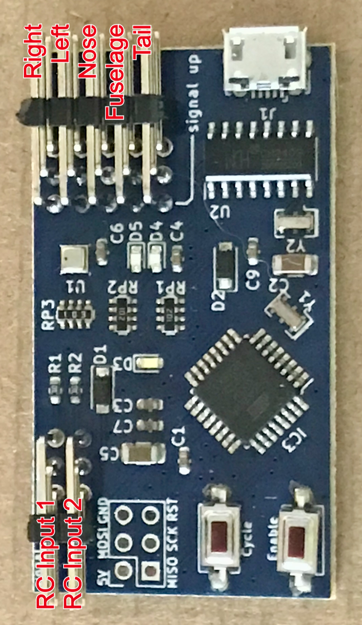
Why are there 2 RC Inputs?
The second input is used for radios that don’t have a knob, but do have a switch that controls an auxiliary channel. It makes it easier for users that only have a 2 or 3 position switch. Some radios don’t set full travel on their switches, so you don’t end up selecting the shows that you expect when using a switch. Using RC Input 2 changes the way it reads the input signal, so if the switch is in the up position, the controller will cycle through the patterns every few seconds. As soon as you move the switch to the down position, the pattern stops on the current one.
Installation and Operation
Installation in the Night Radian
CAUTION: Do not connect power to the system until all the LED strips and the RC control cable have been plugged into the LED controller. If you do, damage can be done to the LED strips and/or the LED controller.
To install the new controller, you will need to remove the distribution connector that is in the belly of the plane, under the hatch. First remove the hatch by squeezing the pins together at the hinge so they slide out. Grasp all of the connectors that are plugged into the connector block in the fuselage, rock it back and forth to break free the adhesive on the bottom of the block, and gently pull the connector block out of the fuselage. Then disconnect all the LED connectors from the connector block. Next you will need to thread the new cable that came with the Radian LED Controller through the passage in the fuselage. The easiest way to do this is by taping it to the connector of the original LED controller that you unplugged from the connector block, and using that to carefully pull the new cable through the passage. This cable will need to be plugged into a spare channel in your radio receiver. The other end will connect to the RC input pins on the new Radian LED Controller. If your transmitter has a rotary knob, connect the cable to RC Chan 1 Input. If your transmitter does not have a rotary knob and you want to use a 2 or 3 position switch, connect the cable to RC Chan 2 Input. Once the cable is connected, plug the LED connectors from each of the LED strings into the correct output pins of the controller. On all connections to the new controller, the signal pins (usually white or light brown wire) are the pins farthest away from the board. Tuck the LED Controller into the forward area of the hatch with the LED output pins pointing toward the rear of the plane, and the programming buttons facing up. Replace the hatch by squeezing the pins so they slide into the hinge. You are now ready to power up your plane and test out the LED Controller.
Configuration - Enabling and disabling the NAV lights
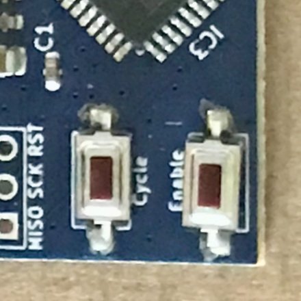
The navigation light option is enabled by default on the LED Controller. If you want to disable it, press and hold the Enable/Disable button for a few seconds. It can be re-enabled by repeating this action.
Configuration - LED Show Selection
There are several shows programmed into the LED Controller, and they are all enabled by default. With a rotary knob on your transmitter, you can slowly cycle through all the different shows. If you don’t have a rotary knob, you can assign the channel to a 3-position, or even a 2-position switch. Then you simply flip the switch down to cycle through all the shows, every few seconds, and when you want to stay on the current show, flip the switch up. You can also enable or disable any of the shows by entering programming mode. This is completely optional, and not necessary for normal operation.
To enter programming mode on the LED Controller, hold down the Cycle button for a few seconds. The LEDs will all flash to indicate that programming mode has been entered. You can then click the Cycle button to cycle through all the available shows. The LEDs will flash either green or red to indicate if that show is enabled or disabled. You can change the enabled/disabled state of any show by clicking the Enable button while on that show. When changing the state, the LEDs will flash red or green to indicate that you have changed the state of that show. When you reach the end of the shows, it will cycle back to the beginning again. When you are finished choosing which shows you want to use, hold down the Cycle button for a few seconds. The LEDs will all flash to indicate that programming mode has been exited, and your changes have been saved. If you don’t exit program mode correctly (i.e. removing power), your changes will not be saved.
Firmware updates
The code that runs the Wingnut Tech LED Controller has been a work-in-progress over the last couple of years, and as such, continues to evolve over time. We occasionally add features or new shows, improve performance, or find and fix bugs.
We also added the ability to easily customize the settings of the controller to allow for custom builds with different lengths of LED strips.
Configuring/Downloading
-
Go to the online configurator tool. It will have the most recent firmware version that works for all board revisions.
-
If you just want the default Night Radian settings, leave all settings at default. Otherwise, adjust as needed.
-
In the dropdown box at the bottom of the page, select the board revision you have, then select:
-
Firmware+Config - this includes the current firmware version, plus the setting you’ve set on the page
-
Firmware only - this just includes the current firmware, leaving any current config on your controller intact
-
Config only - this includes just the config changes you’ve made, leaving the current firmware on your controller intact
-
Flashing
V2 boards:
After downloading, you should end up with a .uf2 file.
-
Hold down the "Boot" button on the board while plugging it in to your computer via USB.
-
Drag-and-drop or copy/paste the .uf2 file into the "RPI-RP2" drive that shows up.
V1 boards:
After downloading, you should end up with a .hex file.
-
You will need to download our HEX Uploader program to flash V1 boards.
-
Under the Assets section of the latest release, download the correct version for your operating system.
-
Unzip the file anywhere on your computer and run it. You may have to click through warnings about running the program.
-
-
In the HEX Uploader tool, browse to the .hex file you downloaded, choose the right COM port, and hit Flash Firmware.